my cheat sheet modern network fabrics
1 Background
For many years layer 2 networks solved loop problems with the spanning tree
protocol, stp, ieee 8021D, which calculated a least spanning tree with a root
tree based on the lowest bridge id, and a minimal spanning tree built from that
root.
Any change to the topology with a new switch being inserted, or a switch leaving the tree (shut down) or link state change between bridges would cause the spanning tree to block all traffic while the new minimal spanning tree with root bridge selection process would complete. States for l2 links were:
- blocking
- listening
- learning
- forwarding
- disabled
1.1 BPDU
Switches communicated their states by sending bpdu packets, bridge protocol data
units.
1.2 STP shortcommings
The two biggest issues with spanning tree protocol is 1) switches typically take 40 seconds to fully transition from a state change to forwarding packets again. 2) any stp errors by any switch in the network can cause a L2 loop that very quickly, exponentially in fact bring a network down with packets getting duplicated til the links are saturated.
1.3 Flooding BUM Traffic
L2 networks support end devices discovering other L2 end devices by sending
broadcasts. A basic example is a arp broadcast for an ip address. Switches
that do NOT yet have the destination MAC address in its TCAM tables will flood
the broadcast out all ports. Unknown packets get the same treatment. When a
switch sees a packet with a source MAC address it does not yet know, it will
take that opportunity to record which port that new MAC address packet arrived
from. Thus learning and populating a TCAM table where each MAC address should
be sent to. This is called source based learning based on the source mac addr
1.4 taming stp
Throughout the years many ancillary techniques were used to tame stp to be more resilient. Techniques used
- rapid spanning tree (
rstp) (took 40 seconds down to a few seconds of outage by pre-calculating alternative links to bring up immediately when main link would go down. These included:uplink fastport fastbackbone fast
- fixing which switch would be the
root switch. Root switches should be the actual core switches where traffic should flow through, and not some edge access switch that does not have the capacity handle all traffic - restricting which ports will even accept bpdus thus preventing stp recalculation
- parallel link or dual switch protocols that avoids spanning tree on certain
links.
Examples include:
vpc(virtual port channel)mcec(multi-chassis ether-channel)lag(link aggregation protocol)mlag(multi-chassis lag)pvst+(per vlan spanning tree)- ether-channel
vss(virtual switch system)
1.5 avoid stp altogether.
A newer approach is to move away from stp altogether. The replacement protocol is still tasked with these fundamental tasks.
- Must allow for redundant paths with automatic failover for resiliency
- Must allow for parallel links when more bandwidth is needed
- Must allow automatic discovery of end nodes and broadcast traffic
- Must learn where each new MAC address seen on the network should be sent. Ideally without resorting to bum traffic flooding.
2 stp replacement
There are several ways to approach the problem, most often starting with prorietary methods, but typically moving to standards based approaches when they become available.
The following table shows some key techniques and their approach
| Company / | control | New MAC addr | ||||
|---|---|---|---|---|---|---|
| Method | Encapsulation | Standard | plane | Learning Method | default gw | multipath |
| Fabric | MAC in MAC | (TRILL +) | L3 | 2 FTag trees are | to ODMAC | Up to 16 |
| Paths | L2 in L2 | cisco | IS-IS | built by IS-IS | ECMP | |
| (sw. to sw.) | BUM is flooded to | |||||
| 1 FTag and multicast | ||||||
| flooded to other | ||||||
| FTag. | ||||||
| LISP | ip in ip | IGP | EIDs to RLOC mapping | |||
| by ETR and ITR | saved in MS (mapping | |||||
| server) | ||||||
| VXLAN | mac in ip(udp) | ieee | source VTEP sends | |||
| VTEPs encap | unknown MAC to multicast | anycast | ||||
| L2 frames with VNID | group. All VTEPs join | |||||
| and source VTEP ip | this group. Correct dest | |||||
| VTEP replies (if on same VNID | ||||||
| and knows dmac) | ||||||
| VXLAN | mac in ip | newer ieee | MP-BGP | Uses Head End Replication, in | ||
| the control plane. The VTEP | ||||||
| duplicates/copies the BUM | ||||||
| packet and sends to all other | ||||||
| VTEPs. (multicast scales | ||||||
| better) b | ||||||
| VXLAN | ||||||
| GPO | ||||||
| SDA | LISP |
3 Conversational learning
A switch will learn and store a MAC address destination ONLY for packets that actually pass through it. Packets striclty traversing other swirches are never learned. This allows for greater scale, faster learning, and better performance.
For locally connected MAC addresses, the switch learns the MAC address as usual. For remote MAC addresses (form devices connected to other fabric path swtiches), the switch does NOT bother to learn a remote MAC source address unless the dmac is known (typically local). Only when a packet is seen with a destination MAC address known will the switch record the source MAC address as well. Thereby only remembering address that are actually used by the switch. This matches the 3-way handshake nicely.
This will automatically solve the MAC addr flooding denial of service attack where a compromised host floods broadcasts with random source mac addresses. Regular STP switches would fill their TCAM tables with these bogus mac addresses.
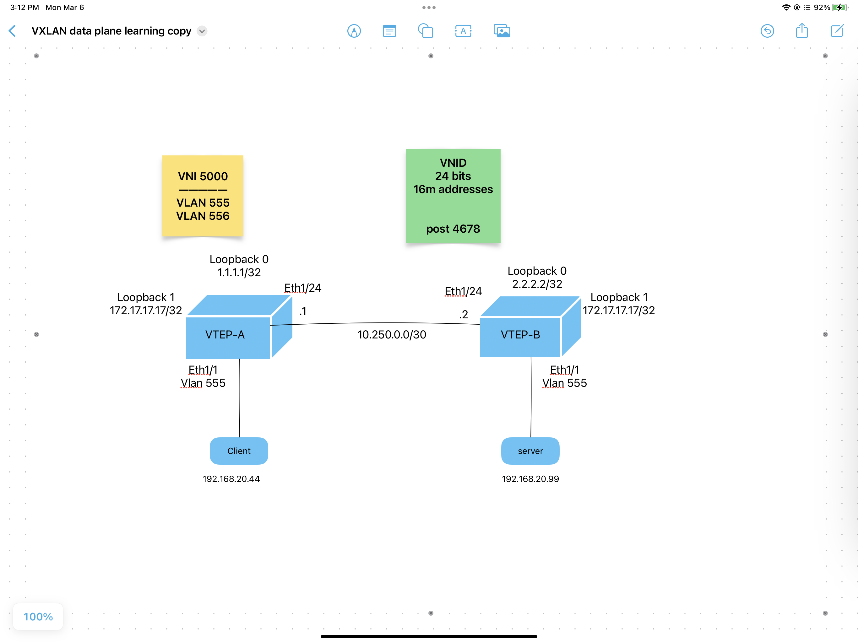
4 VXLAN
Core is a L3 core that passes UDP frames from source to destintion VTEP, VXLAN
Tunnel End Point. The ingress VTEP encapsulates the L2 frames in IP-UDP frames
with the destination IP address of the egress VTEP. The egress VTEP strips the
IP header and forwards the L2 frame to the destination.
But how does the ingress VTEP know that the destination MAC addr of the L2 packet should be sent to a particular egress VTEP? The next section on address learning shows you.
4.1 Address Learning
VXLAN can use data plane learning, as in traditional ethernet, where BUM traffic
is flooded out all interfaces. Or VXLAN can use control plane learningg, which
is more complicated but much more efficient. Control plane learning uses BGP to
distribute reachability information to all BGP peers, but instead of IP prefixes
being distributed, it is L2 MAC addresses and ARP info that is distributed.
Remember that there are you can split up L2 packets into two types, I, known
unicast traffic, where the packet has a destination MAC that is known, and
II, BUM traffic which is broadcast, unknown unicast, and multicast traffic.
Known unicast traffic by definition is known, so a simple lookup tells the
switch where to send traffic.
VXLAN handles BUM traffic in one of two ways, through multicast, or through
headend replication
4.1.1 Multicast for BUM traffic
VXLAN creates a mapping of a multicast group to each VXLAN, i.e. VNI
or VXLAN Network ID. For example:
| VNI | Mcast Group |
|---|---|
| 678 | 224.0.2.5 |
| 17 | 224.0.2.17 |
| 1501 | 224.0.2.1 |
| 41214 | 224.0.2.14 |
| 18 | 224.0.2.18 |
Each VNI maps to a single Mcast group, however multiple VNIs can map to the
same multicast group. i.e. the Mcast groups can be shared.
For each VNI present on a VTEP, that VTEP will join the corresponding Mcast group. And only those multicast groups.
Finally an ingress VTEP that receives a BUM packet on a VNI, will forward
that BUM packet to the appropriate Mcast group.
4.1.2 Headend Replication for BUM traffic
The ingress VTEP is also called the "Headend" VTEP. So when the ingress VTEP
receives a BUM packet on a particular VNI, it makes a copy of that packet, or
"replicates" the packet as a unicast packet for each remote VTEP that has that
same VNI.
Because VTEPs are making copies of packets, for each remote VTEP on that same
VNI, this really works for smaller networks, up to 20 VTEPs. To scale on
bigger networks, use Mcast. Headend replication is easier to configure though,
as you do not need any multicast setup.
4.2 Data Plane Learning
BUM packets arrive on the data plane on a given VNI, and are flooded out to a
multicast group for that particular VNI. Thus each remote VTEP that has joined
that multicast group will receive that BUM packet.
A couple of drawbacks to data plane learning are:
- ONLY works for bridged, L2 traffic
- To route to a different subnet (different VNI) you have to use an external router, which means you have to trombone to a VTEP that supports L3 interfaces on multiple VNIs
- Less secure as a rouge VTEP could announce itself as a default gw for internet traffic, thus able to insert itself as a MIM router for traffic. i.e. in data plane learning there is no authentication of VTEPs.
4.2.1 Configuration with Data Plane learning
this is easier, but not preferred. see Configuring Control Plane Learning for a more scalable solution
- enable features
feature ospf    # needed by the underlay
feature pim     # needed for multicast
feature nv overlay   # enables VXLAN (network virtualization)
# ignore the warning about routing template

feature vn-segment-vlan-based   # lets you tag frames with VXLAN header


router ospf 50
- set MTU
system jumbomtu 9216

system routing template-vxlan-scale  # not needed with newer NXOS versions
# will need save config and reboot router for this change.
- map VLAN to VNI
vlan 555
  # vlan 555 for regular hosts
  vn-segment 5000      # maps vlan 555 to vxlan 5000
- routed link (underlay)
interface eth 1/24
no switchport                    # makes it a routed link
ip address 10.250.0.1/30
ip router opsf 50 area 0         # routing for the underlay
ip pim sparse-mode               # needed for multicast over the underlay
no shut
At this point the ospf backbone should be up.
- host port Nothing special here. Just a plain access point on a vlan
int eth 1/1
description end device, maybe a laptop or a server.  No VXLAN configs here
switchport
switchport access vlan 555
no shut
- loopback interfaces
# needed for both rendezvous point for multicast and VTEP ip address

interface loopback 0
description  VTEP gets its ip address from the loopback interface
ip address 1.1.1.1/32
ip router ospf 50 area 0
ip pim sparse-mode


interface loopback 1
description for multicast rendezvous point  #SAME on all hosts i.e. anycast ip addr
ip address 172.17.17.17/32
ip router ospf 50 area 0
ip pim sparse-mode
- setup multicast for the underlay:
7.1) setup rendezvous point, this time based on the loopback 1 interface 172.17.17.17 the loopback 1 interface has the SAME 172.17.17.17 address on both swtiches as it is an anycast gateway.
ip pim rp-address 172.17.17.17 group-list 224.0.0.0/4   # same on all VTEPs

# the anycast ip address is bound to the real ip address.  So assuming the
# other two VTEPs have addresses 2.2.2.2 and 3.3.3.3 (loopback 0) then:
ip pim anycast-rp 172.17.17.17 1.1.1.1
ip pim anycast-rp 172.17.17.17 2.2.2.2
ip pim anycast-rp 172.17.17.17 3.3.3.3
- create the VTEP interface that encapsulates the L2 traffic
This interface config would be identical on all VTEPs. i.e. they each have an
nve1interface mapped to the local loopback 0 interface, and for each VTEP participating inVNI 5000they need to join the same mcast group, in this case230.1.55.55interface nve1 # on the Nexus platform description ip addr is from loopback 0 Also where VNIs mapped to multicast groups no shut source-interface loopback 0 member vni 5000 mcast-group 230.1.55.55 # where BUM traffic is sent
- Confirming:
show nve interface

show nve peers
# initially won't show any peers, until a host initiates a broadcast.  Then
# that broadcast is flooded onto the multicast group and the VTEPs will see
each other.

show nve vni
# will show the multicast group associated with the VNI and its state
# mode is DP for data plane learning
Other troubleshooting commands:
show nve interface
show nve vni
show nve peers    # shows VTEP peers, but these are cached and will time-out
                  # with no traffic.
4.3 control plane learning
switches will learn mac addresses ahead of time, using bgp. each vtep will take
any new mac address that it learns about locally, and forward that information
to all other bgp peers. thus every vtep will know every mac address on every
other vtep, for each vni that it is routing for.
4.3.1 bgp address families
some background on bgp. bgp can share reachability information for different
protocols. these are called different address families. the first one was
ipv4, followed soon after by ipv6 address families, and vpn address families for
mpls. but bgp also supports sharing evpn address families.
4.3.2 bgp control plane learning
each vtep runs bgp and peers with each other vtep using ibgp, thus as a full
mesh peering to all other vteps, which dictates having actually (n*(n-1)/2 peers.
beyond 8 or 9 vteps this full mesh becomes too cumbersome, just bgp also
supports bgp route reflectors where each vtep peers only with two or several bgp
peers, known as bgp route reflectors. the router reflectors will handle
replicating the learned reachability info to all of its peers, so all vteps will
get all the information, without having to create the n-squared peering.
when vteps are learned via bgp, they get authenticated, and are thus trusted. all other vteps coming online are not trusted. that is another benefit to using control plane learning via bgp.
4.3.3 arps
when a host sends out its first arp packet the local switch, i.e. ingress vtep
will suppress that arp and just reply immediately to the host asking. it can
do that because it already knows 1) where the destination mac resides, as well
as its ip address. thus the reachability info that each vtep learns is both
the mac addr as well as the ip addr related to that mac addr.
so each ingress vtep seeing a host for the first time, typically an arp request, that ingress vtep sends both the mac address and ip address to all of its bgp peers, along with its own vtep id, so all other vteps know both mac address and arp information.
4.3.4 bum traffic when control planning being used
although every vtep will have learned of every mac and ip address on each vni, there are still times where a host will send a broadcast, unknown unicast or multicast packet. vxlan will use either 1) Headend Replication for BUM traffic or2) Multicast for BUM traffic to send bum traffic to all remote vteps.
4.4 Configuring Control Plane Learning
This configuration is slightly more complex than Configuration with Data Plane learning Particularly we will use headend replication (not multicast)
4.4.1 Configure the underlay
- enable features
feature ospf    # needed by the underlay

router ospf 50
- set MTU
system jumbomtu 9216
- routed link (underlay)
interface eth 1/24
description routed backbone for underlay in OSFP area 0
no switchport                    # makes it a routed link
ip address 10.250.0.1/30
ip router opsf 50 area 0         # routing for the underlay
no shut
- loopback interfaces
# needed for both VTEP ip address

interface loopback 0
description  VTEP gets its ip address from the loopback interface
ip address 1.1.1.1/32
ip router ospf 50 area 0
At this point the ospf backbone should be up.
4.4.2 configure the overlay
This time we need bgp as that will share EVPN reachablity info between VTEPs. i.e. each MAC addr and ARP entry of local VTEP gets diseminated to all other VTEPs
- Turn on features we need
feature bgp
 feature interface-vlan     # same as when we want to create SVIs (switched
                           # virtual interfaces)  Here we  use it to
                           # create a virtual  anycast gateway interface
feature vn-segment-vlan-based   # lets you tag frames with VXLAN header
feature nv overlay         # enables VXLAN (network virtualization)
nv overlay evpn            # adds the evpn address family
- Configure the anycast gateway on all VTEPs It is the SAME vmac on all switches, so I like to pick one easy to remember.
fabric forwarding anycast-gateway-mac dead.beaf.cafe
- create the VTEP interface that encapsulates the L2 traffic
This interface config would be identical on all VTEPs. i.e. they each have an
nve1 interface mapped to the local loopback 0 interface, and for each VTEP
participating in VNI 5000 they need to join the same mcast group, in this
case 230.1.55.55
interface nve1           # on the Nexus platform
  description nve1 ip addr is from loopback 0    Also use bgp to learn hosts
  source-interface loopback 0
  host-reachability protocol bgp    # enables control plane learning on VTEP
  no shut
- each VTEP needs to be running BGP
router bgp 65535    # private AS number
router-id 1.1.1.1   # i.e. the loopback0 interface
neighbour 2.2.2.2   # statically specify the other VTEPs that you will peer with
  remote-as 65535   # same AS number so will be iBGP
  update-source loopback0
  address-family l2vpn evpn       # tells bgp to share L2 reachability to peer
    send-community                # uses communities to send L2 reachablity
    send-community extended       # and route target info the bgp neighbours
neighbour 3.3.3.3
  remote-as 65535
  update-source loopback0
  address-family l2vpn evpn       # tells bgp to share L2 reachability to peer
    send-community
    send-community extended
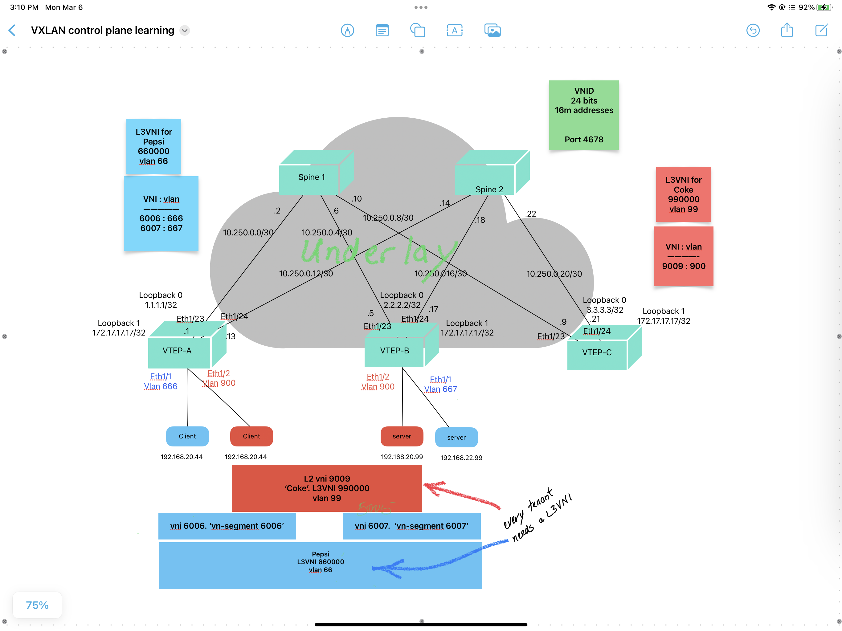
4.4.3 Add a tenant
- create a
L3VNIby creating a vlan first. This allows routing on the local switch and lets you attach it to aVRF. This case theL3VNIis660000and its associated vlan is66# on both vtep a and vtep b for Pepsi L3VNI vlan 66 description vlan for Pepsi L3VNI 660000 Will have a matching int vlan 66 vn-segment 660000 # vrf member is configed on the matching l3 int vlan 66 # on both vtep a and vtep b for Coke L3VNI vlan 99 description vlan for Coke L3VNI 990000 Will have a matching int vlan 99 vn-segment 990000 # vrf member is configured on the matching l3 int vlan 99 # Identical on all VTEPS that need that vrf
- create a VRF per tenant, and route distinguishers and route targets RD and RT
vrf context Pepsi
  vni 660000           # adds the Pepsi L3VNI 660000 to the Pepsi VRF
  rd auto
  # adding route distinguishers to keep the vrf unique in the bgp database.
  # If you are peering with non-cisco, best to manually set the rd value,
  # Here we can leave it auto, which lets the switch assign the rd automatically

  # route targets are used to both import and export routes and in this case
  # evpn addresses for Pepsi
  address-family ipv4 unicast
     route-target both auto     # auto lets the switch pick a unique value
     route-target both auto evpn

  # identical on vtep 1 and vtep 2, just not shown here.

vrf context Coke
  vni 990000
  rd auto
  address-family ipv4 unicast
     route-target both auto
     route-target both auto evpn
Recapping BGP: BGP rd and rt lets you control sharing routing info and MAC address between peers, while still keeping them isoated to a particular VRF/ tenant. It works like this:
a) exporting marks the routes from the local vrf bgp database with the route target value you want for a tenant
b) bgp peers receive these routes and look for the RT values that they would like to import for the tenants on this VTEP.
c) the imported routes are thus added to the appropriate vrf (based on the matching RT markings)
- create the
sviinterfaces for anyl3vni vlans, in this case66(and later99)
int vlan 66
   no shut
   vrf member Pepsi
   ip forward        # essentially turns on routing


int vlan 99
   no shut
   vrf member Coke
   ip forward        # even if this is a l2 ethernet interface, you will need this
                     # to route to other subnets, like the internet.
   # if truly you only need bridging here then  no need for "ip forward"  confirm this
- configure the VTEP, which is done differently from the data plane approach,
including
ARP suppressionandhead-end replicationint nve1 description VTEP or network virtualized edge, nve, switch member vni 6006 suppress-arp # this lets local switch to just answer any and all arp # broadcasts directly, since all VTEPs have their any-cast # gateway locally ingress-replication protocol bgp # this is the head-end replication member vni 6007 suppress-arp ingress-replication protocol bgp member vni 660000 associate-vrf # tells the VTEP that the vni 660000 # is used for routing member vni 9009 suppress-arp ingress-replication protocol bgp member vni 990000 associate-vrfContinuing with BGP additions:
router bgp 65535
   vrf Pepsi
       address-family ipv4 unicast
          advertise l2vpn evpn
          # this allows external routes to be advertised as L3 routes within
          # the vrf, in  this case Pepsi.
# identical on all vteps with Pepsi vrf
- create client vlans and associated vnis i.e. to vxlan network identifiers
# on vtep-a
vlan 666
  description part of Pepsi clients
  # this is the vlan 666 for L3VNI, for "Pepsi".  I add int vlan 666 later
  vn-segment 6006      # maps vlan 666 to vxlan 6006  i.e. vni 6006

# on vtep-b
vlan 667
  description part of Pepsi clients
  # this is a L3VNI, for "Pepsi". actaully just the VLAN, I add int vlan 666 later
  vn-segment 6007      # maps vlan 666 to vxlan 6007  i.e.  vni 6007


# note: vtep-b could also have vlan 666, for for Pepsi they wanted two separate
# vlans, thus routing between vla n  666 and vlan 667
- create the L3 interface vlan (i.e. SVI) that is associated with the L3VNI as
well as a customer's VRF
int vlan 666
  description the SVI for Pepsi, i.e. vlan 666 that was created earlier
  no shut
  vrf member Pepsi
  ip address 192.168.20.1/24
  fabric forwarding mode anycast-gateway    # same anycast gw on all vteps

# identical on vtep 1 and vtep 2

int vlan 667
  description the other SVI for Pepsi, i.e. vlan 667 that was created earlier
  vrf member Pepsi
  ip address 192.168.22.1/24
  fabric forwarding mode anycast-gateway    # same anycast gw on all vteps


int vlan 900
   description Coke vlan
   no shut
   vrf member Coke
   #  ip addr for anycast gateway is added even if Coke does not need to
   #  route between vlans.  That is because the anycast gateway is always
   #  the default gw to get to any outside L3 network
   ip addr 172.16.99.1/24
   fabric forwarding mode anycast-gateway
- configure anycast gateway
- finally configure the EVPN i.e. vteps for each tenant
evpn
# used to advertise MAC address reachablity in BGP
  vni 6006 l2    # or l2 information
      rd auto
      route-target import auto
      route-target export auto
# identical on all vteps

  vni 6007 l2
      rd auto
      route-target import auto
      route-target export auto

  vni 9009 l2
      rd auto
      route-target import auto
      route-target export auto
- configure edge ports connecting to end devices
int eth 1/1
description Pepsi end device, maybe a laptop or a server.  No VXLAN configs here.
switchport
switchport access vlan 666
no shut

int eth 1/2
description Coke end device, maybe a laptop or a server.  No VXLAN configs here.
switchport
switchport access vlan 900
no shut

int eth1/3
description  other vlan on the Pepsi client facing interface
switchport
switchport access vlan 667
no shut
- Confirming:
show nve interface

show nve peers
# initially won't show any peers, until a host initiates a broadcast.  Then
# that broadcast is flooded onto the multicast group and the VTEPs will see
each other.

show nve vni
# will show the multicast group associated with the VNI and its state
# mode is DP for data plane learning
4.4.4
5 routing and multitenancy vxlan evpn
vxlan evpn supports irb, (integrated routing and bridging) as well as multitenancy
5.1 irb
with data plane learning, as discussed above, you need an external router when
traffic passes from one vlan/subnet to another. with vxlan-bpg-evpn, i.e.
control plane learning, both layer 2 l2vni and layer 3 l3vni vnis can be
created. you specify the type of vni when you create it. l2vpn pass traffic
within the same l2 vni, i.e. bridging traffic. l3vni let you route traffic from
one vni to another vni. l3vnis are optional, as you can still use external
routers to route traffic, but if you want the local vtep to route traffic, then
you need a l3vni
each vtep needs to know only the l2vnis that are local to it. however all vteps
need to know all l3vni networks. this is a requirement for all vteps to
support anycast gateway, where all vteps present themselves as the l3 gateway to
local hosts, and then route traffic to the l3 destination.
could not,
5.2 anycast gateway
with l3vnis each vtep presents itself as the l3 gateway to end hosts. all vteps
present the same ip address and mac address for each anycast gateway,
so hosts can easily move between vteps and retain their arp table. vms can
move between vteps very easily. they do not even need to re-arp for their
default gateway.
5.3 multitenancy
to create an isolated network, say for pepsi, simply map the pepsi l3vni to the
pepsi vrf. and the coke l3vni to the coke vrf.
| vrf-1 | vrf-2 | vrf-3 | |
|---|---|---|---|
| customer/tenant | pepsi | coke | maple leaf foods |
| vni 9000 | |||
| L3VNI 99000 | |||
| route | 65000:5 | 65000:10 | 65000:20 |
| distinguisher | |||
| route targets | export 65000:10 | export 65000:10 | export 65000:10 |
| import 65000:10 | import 65000:10 | import 65000:10 | |
| l3vni | 660000 | 990000 | 1111111 |
| associated vlan | 66 | 99 | 111 |
| client vlans | 666, 667 | 900 | not yet configed |
| client ip addr | 192.168.20.0/24 | 192.168.20.0/24 | 10.55.66.0/24 |
| subnets | 192.168.22.0/24 |
Many VNIs can be associated with a tenant, or customer.
** unfinished. check back later.